 Before dismantling. 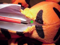 The covering has a velcro strip for access to the battery compartment and the power switch. But to remove the covering further required an unpick (stitching removal tool). The green dot is the first casing screw location. 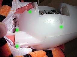 Removing the cover exposes the casing. The legs have screws, as does the tail and the body. The tail screws are different to the rest; they have a wider head. 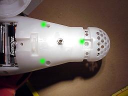 More casing screws. [taken after socket fitted]. 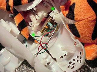 Removing the screws allows the casing to be opened, revealing a control circuit board and a motor. The green dots show the screws holding the PCB down. 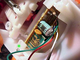 A top view of the PCB. The vertically mounted module is where the intelligence is, the rest of the circuit is interface and drivers. Note the protrusion on the white plastic moving section; this hits the PCB underside when the feet are compressed. 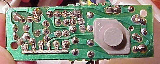 The underside of the PCB after removal. The grey pushbutton is a rubber casing over a carbon blob which shorts out an array of copper tracks on the PCB, starting the sequence. Figuring out which tracks related took a bit of prying under the rubber casing with a continuity tester. 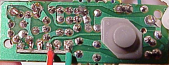 New cabling attached to the relevant points on the PCB. Connecting the two wires now started the sequence. The green wire was attached to the positive supply, the red one to the signal input. 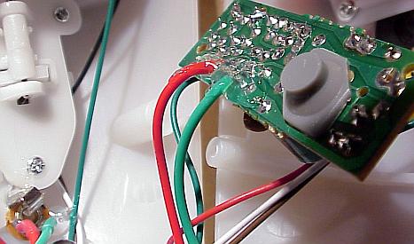 Hot glue was used as a cable restraint for the new PCB wires. 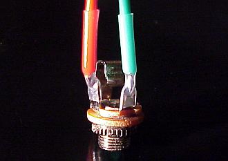 The wires were then attached to the newly installed panel socket. Heat shrink was used on the socket. 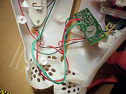 There is ample space within the casing for the wires. |